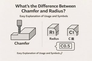
On mechanical drawings you’ll often see notes such as C1, C0.5, or R1.
These symbols specify how to finish an edge (a corner). However, a C-edge (chamfer) and an R-edge (radius/fillet) have very different purposes and final results.
This article explains the difference between chamfering (C) and radiusing (R), how to read the drawing notation, typical machining methods, and practical selection guidelines—written for beginners.
What Is a C-Edge (Chamfer)?
A C-edge is a chamfer created by cutting the corner at 45° to form a flat, angled surface.
On drawings it is typically specified like this:
C1, C0.5, C2 …
This means “a 1 mm chamfer at 45°,” “a 0.5 mm chamfer,” and so on.
● Why C-Edges Are Used
- Deburring sharp edges (improves safety)
- Improves insertion/assembly (lead-in)
- Reduces unevenness in coating/plating near edges
- Helps prevent edge chipping
Chamfering is the most common edge treatment and is used on most machined parts.
What Is an R-Edge (Radius / Fillet)?
An R-edge is an edge finished with a rounded radius (a fillet).
On drawings it is typically specified like this:
R1, R0.5, R2 …
This means “a 1 mm radius,” “a 2 mm radius,” etc.
● Why R-Edges Are Used
- Reduces stress concentration and helps prevent fatigue failure
- Reduces wear on sliding/contact surfaces
- Improves impact resistance at outer edges
- Improves material flow in resin parts and molds
R-edges are often specified where strength and functional performance are critical.
C vs. R: Key Differences (Comparison Table)
| Item | C-Edge (Chamfer) | R-Edge (Radius) |
|---|---|---|
| Shape | Straight 45° cut | Arc-shaped rounding |
| Main purpose | Deburring / easier insertion | Higher strength / lower stress concentration |
| Typical machining | Chamfer tool / deburring | Ball end mill / radius cutter |
| Characteristics | Fast machining, lower cost | Takes more time to machine |
| Common use | General metal parts | High-strength parts, plastics, molds |
How to Read Drawing Notes (and Practical Cautions)
① Never confuse C and R
C1 and R1 are completely different requirements.
② Micro-chamfers such as “C0.2”
Small chamfers are often used as a deburring/edge-break finish.
③ R-features may require NC programming
Especially R0.5 or smaller can be considered precision machining and may increase setup/programming work.
④ R-edges affect sealing and sliding performance
R specifications can be critical for O-ring seats, sliding blocks, and similar functional surfaces.
⑤ “No chamfer specified” means a sharp edge—this can be risky
Sharp edges can cause injury, chipping, and stress concentration. As a rule of thumb, at least C0.3 (or an equivalent edge break) is often recommended unless there is a reason to keep the edge sharp.
Typical Machining Methods
● How C-Edges Are Made
- Chamfer cutter
- Side cutting with an end mill
- Deburring tools
● How R-Edges Are Made
- Radius (R) cutter
- Ball end mill
- Hand finishing (common for plastics/aluminum)
In many cases, R-machining tends to cost more than chamfering due to toolpath time and finishing requirements.
How to Choose: When to Use C vs. R
● Use a C-Edge (Chamfer) when:
- General edge treatment for metal parts
- Assembly/insertion is important
- You want to keep cost down
● Use an R-Edge (Radius) when:
- Stress concentration is a concern
- Cracking is a risk (plastics, aluminum, thin sections)
- Sliding or sealing performance matters
- Aesthetic appearance is important
Recommended Books
- Introductory books on machining
- Mold finishing and edge treatment
- How to read machining drawings and instructions
Conclusion
Chamfers (C) and radii (R) may look similar at a glance, but their purpose and machining methods are different.
- C = break the edge with a 45° flat (deburring, lead-in)
- R = round the edge (strength, stress reduction)
- Select based on function and application requirements
- R-features often increase cost due to machining time
By getting comfortable reading these drawing notes, you can prevent machining issues and assembly problems before they happen.